
Analog systems and applications, lecture — XI.
Bridge type full wave rectifier.
This article belongs to a series of lectures on analog electronics, the paper goes by the name “Analog Systems and Applications” for the physics honors degree class. All lectures of this series will be found here. This comprises of the 11th lecture of the series. The lecture was delivered on 12th February 2018.
In our last lecture we discussed the center tapped full wave rectifier and derived its most important parameters. Check that lecture for a conceptual continuity with the present lecture. Prior to that we discussed in much detail the case of the half wave rectifier and its parameters. Those two lectures can be accessed here.
Today we will discuss the other type of full wave rectifier, viz. bridge type rectifier. Lets draw a suitable diagram for the same and discuss its operational ideas.
The bridge type full wave rectifier
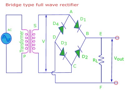
(i) It consists of 4 diodes D1, D2, D3 and D4.
(ii) Diagonally opposite corners ‘A‘ and ‘C‘ are connected across the secondary ‘S‘ of the power transformer. Diagonally opposite corners ‘B‘ and ‘D‘ are connected to the load resistance ‘RL‘.
(iii) During positive or first half cycle D1, and D3 conduct as A is positive wrt C. During negative half cycle or second half of signal D2, and D4 conduct as C is positive wrt A.
(iv) Bridge rectifier does not require center-tapping at the secondary of the transformer.
Let the voltage across the secondary of the transformer be given by V = V0 sin ωt. Here V0 is the maximum transformer voltage or amplitude of voltage signal. Also ω/2π is the frequency of the AC signal.
(i) During the half cycle when A is positive relative to C; D1, and D3 are “forward biased”, D2, and D4 are “reverse biased”. iL1 flows through RL, in the direction ABEFDCSA. iL2 = 0.
(ii) Similarly during next-half cycle C is positive relative to A; D2, and D4 are “forward biased”, D1, and D3 are “reverse biased”. iL2 flows through RL, in the direction CBEFDASC. iL1 = 0.
Thus current always flows in the same direction; along EF, through RL.
Lets write down the current.


AND


So maximum current through load is 
The average or dc and rms value of current, rectifier efficiency and ripple factor can be given by comparing with the same of a center-tapped full wave rectifier.
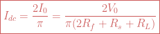
![\boxed{V_{dc}=\frac{2V_0}{\pi \big[1+\frac{2R_f+R_s}{R_L} \big]}}](https://s0.wp.com/latex.php?latex=%5Cboxed%7BV_%7Bdc%7D%3D%5Cfrac%7B2V_0%7D%7B%5Cpi+%5Cbig%5B1%2B%5Cfrac%7B2R_f%2BR_s%7D%7BR_L%7D+%5Cbig%5D%7D%7D+&bg=ffffff&fg=cd5c5c&s=0&c=20201002)

Rectifier efficiency (in %) is given by 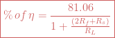
Ripple factor is 
PIV across each diode is now V0 {instead of 2V0}.
Advantage.
(i) Small transformer can be used.
(ii) Center-tap on secondary of transformer is not required.
(iii) PIV per diode is V0, instead of 2V0 for center-tapped full wave rectifier. This is helpful when higher voltage is required.
(iv) TUF (transformer utilization factor) increases to 0.811, current flowing in secondary is purely alternating. This helps for large power delivery.
(v) Low cost.
(vi) High reliability.
Disadvantage.
(i) 2 extra diodes are needed. This increases voltage drop and reduces output voltage. This creates problem when low voltage output is required.
(ii) This has poor voltage regulation compared to center tapped full wave rectifier.

Leave a comment