
Analog systems and applications, lecture — VIII & IX.
Diodes as rectifiers: half-wave rectifiers and their parameters.
This article belongs to a series of lectures on analog electronics, the paper goes by the name “Analog Systems and Applications” for the physics honors degree class. All lectures of this series will be found here. This comprises of the eighth and ninth lecture of the series. The lectures were delivered on 6th and 7th February 2018.
Lecture VIII
Rectification is an arrangement where AC current is converted into unidirectional current by employing diodes. Such devices are known as “rectifiers” and they offer low resistance to the current in a specified direction, while offering very high resistance in the opposite direction.
If a semiconductor diode is supplied with AC current it is “forward biased” during half cycle of the source current and “reverse biased” during the other half cycle of the source current.
The diode acts like a “closed switch” during positive cycle (forward bias) and like an “open switch” during negative cycle (i.e. reverse bias). Such rectifiers where only one “half cycle” is used for biasing the diode “forward” and the other half cycle is used for biasing the diode “reverse” are known as half-wave rectifiers. as such devices replicate only half of the input signal in the output.
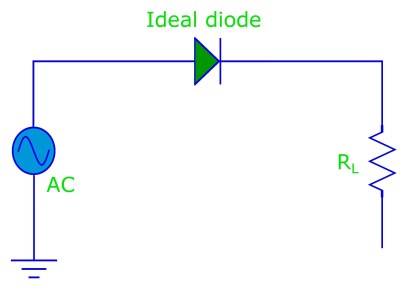
The following diagrams illustrate the half-wave rectifier.
An ideal diode connected to an AC signal and a load resistor.
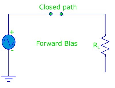
When the diode is in forward bias it acts like a closed switch (i.e. it conducts a current).
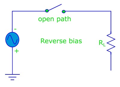
When the diode is in reverse bias it acts like a open switch (i.e. it does not conduct any current).
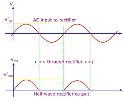
The input and output of a diode half wave rectifier.
Let us now study in detail the voltage and current relations of the half-wave rectifier. For our purpose let us draw a basic circuit diagram for the half-wave rectifier.
The half wave rectifier basic circuit diagram.
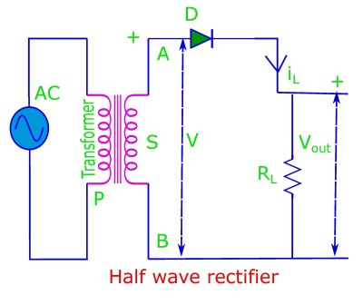
i. For sinusoidal input at the primary of the transformer, the output voltage at the secondary of the transformer is also sinusoidal but with an opposite phase compared to the primary. Let this be given as: V = V0 sin ωt, here V0 is the peak voltage and ω/2π is the frequency.
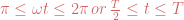
ii. Let Rf be the dynamic forward resistance of the diode, Rs be the resistance of the transformer secondary and RL be the “load resistance”. Instantaneous current iL through the resistance RL would then be given as: 
Thus maximum value of current is: 
Current for the half-wave rectifier is thus given by: 


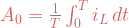
DC or average values.
Average value of current (Iav):
Average value of current (Iav) through the load resistance (RL) is therefore: 
Thus the average or DC value of current is given as: 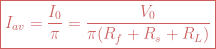
Average value of voltage (Vav):
Average or DC value of voltage (Vav) at the load resistance (RL) is therefore: ![V_{av}=V_{dc}= I_{dc}\times R_L \\ \\= \frac{I_0 R_L}{\pi}=\frac{V_0R_L}{\pi(R_f + R_s+R_L)}\\ \\ =\frac{V_0}{\pi [1+\frac{R_f+R_s}{R_L}]}\\ \\ =\frac{V_0}{\pi}[1+\frac{R_f+R_s}{R_L}]^{-1}\\ \\ \approx \frac{V_0}{\pi}-\frac{V_0}{\pi R_L}(R_f + R_s)\\ \\(for \,R_L >> R_f+R_s)](https://s0.wp.com/latex.php?latex=V_%7Bav%7D%3DV_%7Bdc%7D%3D+I_%7Bdc%7D%5Ctimes+R_L+%5C%5C+%5C%5C%3D+%5Cfrac%7BI_0+R_L%7D%7B%5Cpi%7D%3D%5Cfrac%7BV_0R_L%7D%7B%5Cpi%28R_f+%2B+R_s%2BR_L%29%7D%5C%5C+%5C%5C+%3D%5Cfrac%7BV_0%7D%7B%5Cpi+%5B1%2B%5Cfrac%7BR_f%2BR_s%7D%7BR_L%7D%5D%7D%5C%5C+%5C%5C+%3D%5Cfrac%7BV_0%7D%7B%5Cpi%7D%5B1%2B%5Cfrac%7BR_f%2BR_s%7D%7BR_L%7D%5D%5E%7B-1%7D%5C%5C+%5C%5C+%5Capprox+%5Cfrac%7BV_0%7D%7B%5Cpi%7D-%5Cfrac%7BV_0%7D%7B%5Cpi+R_L%7D%28R_f+%2B+R_s%29%5C%5C+%5C%5C%28for+%5C%2CR_L+%3E%3E+R_f%2BR_s%29&bg=ffffff&fg=cd5c5c&s=1&c=20201002)
Thus for this approximation (RL >> Rf + Rs), 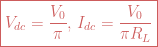
Average value of power (Pav):
Now we can compute the average power across the rectifier load: 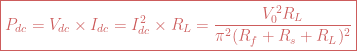
RMS value of current and voltage.
The root-mean-square or effective value of current in the rectifier circuit — passing through the load, can be calculated as follows. 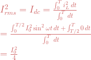
Homework: prove this result by carrying out the integral above.
So 
i. Irms >> Idc, RMS value of half rectified output (Irms = I0/2) is not equal to rms value of AC input (I0/√2).
ii. Load is purely resistive, 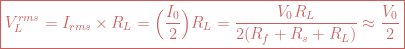
Frequencies of rectified output.
Let us assume that the output at R_L, contains multitude of frequencies, so that we can apply the Fourier analysis. 


When we solve for the constants, we obtain (by using: 
![\boxed{i_L = I_0 \Big[ \frac{1}{\pi} + \frac{1}{2} \sin \omega t -\frac{2}{3\pi}\cos 2 \omega t - \frac{2}{15 \pi}\cos 4 \omega t + ...\Big]}](https://s0.wp.com/latex.php?latex=%5Cboxed%7Bi_L+%3D+I_0+%5CBig%5B+%5Cfrac%7B1%7D%7B%5Cpi%7D+%2B+%5Cfrac%7B1%7D%7B2%7D+%5Csin+%5Comega+t+-%5Cfrac%7B2%7D%7B3%5Cpi%7D%5Ccos+2+%5Comega+t+-+%5Cfrac%7B2%7D%7B15+%5Cpi%7D%5Ccos+4+%5Comega+t+%2B+...%5CBig%5D%7D&bg=ffffff&fg=cd5c5c&s=0&c=20201002)
i. 1st term: 
ii. 2nd term: 
iii. 3rd term: its known as second harmonics.
Thus the half wave rectifier passes AC as well as DC components.
Lecture IX
Rectifier efficiency:
Ratio of rectification or rectifier efficiency is defined as the ratio of the “direct output power” divided by the “alternating input power from transformer secondary”, its denoted by the symbol η.


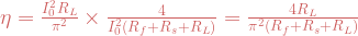

Thus theoretical efficiency of a half-wave rectifier increases as (Rf + Rs)/RL → 0. Maximum value of theoretical efficiency is 40.53 % . But rectifier delivers maximum output power when , RL = Rf + Rs this is known as Maximum Power Theorem. So maximum efficiency of a rectifier (half wave) is actually 20.3 %.
Transformer utilization factor:
The Transformer Utilization Factor (TUF) is defined as the ratio of the DC power delivered to the load to AC rating of the transformer secondary.
So 
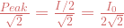
Rated AC power is rated rms voltage of secondary (V0/√2) times actual rms current in secondary (I0/2).
So, 
But V0 = I0 (Rf+ Rs+ RL). So, ![\boxed{TUF =0.287\Bigg[ 1+ \bigg (\frac{R_f+R_s}{R_L} \bigg) \Bigg] ^{-1}=\eta \times 0.707}](https://s0.wp.com/latex.php?latex=%5Cboxed%7BTUF+%3D0.287%5CBigg%5B+1%2B+%5Cbigg+%28%5Cfrac%7BR_f%2BR_s%7D%7BR_L%7D+%5Cbigg%29+%5CBigg%5D+%5E%7B-1%7D%3D%5Ceta+%5Ctimes+0.707%7D&bg=ffffff&fg=cd5c5c&s=0&c=20201002)
Ripple factor:
Ripple factor is defined as the ratio of “effective value of ac components” to the “dc value of the components”. Output current of a rectifier (Irms) consists of direct component (Idc) and effective value of all ac components (I‘rms).


Then ripple factor is given by: 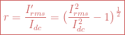
For half wave rectifier: ![\boxed{r = \bigg[\frac{(I_0 / 2)^2}{(I_0/\pi)^2}-1\bigg]^{\frac{1}{2}}=\bigg(\frac{\pi ^2}{4}-1\bigg)^{\frac{1}{2}}=1.21}](https://s0.wp.com/latex.php?latex=%5Cboxed%7Br+%3D+%5Cbigg%5B%5Cfrac%7B%28I_0+%2F+2%29%5E2%7D%7B%28I_0%2F%5Cpi%29%5E2%7D-1%5Cbigg%5D%5E%7B%5Cfrac%7B1%7D%7B2%7D%7D%3D%5Cbigg%28%5Cfrac%7B%5Cpi+%5E2%7D%7B4%7D-1%5Cbigg%29%5E%7B%5Cfrac%7B1%7D%7B2%7D%7D%3D1.21%7D&bg=ffffff&fg=cd5c5c&s=0&c=20201002)
Thus: 
Thus the effective value of ac component of output exceeds the dc value of output. Half wave rectifier is not a suitable device for obtaining dc source.
Peak inverse voltage (PIV):
PIV is defined as the maximum voltage present across the diode ends when teh diode is reverse biased and thus does not conduct. So for half wave rectifier PIV = V0 . For “no breakdown” PIV < PIV (rating).
Voltage regulation:
The ability of a rectifier to maintain a specified output voltage with variation of load resistance is known as voltage regulation.
Thus VR = [output (at no load) – output (at full load)] / output (at full load).
For half wave rectifiers, assuming: RL >> Rf + Rs: ![V_{dc} = \frac{V_0}{\pi \big[ 1 + \frac{R_f+R_s}{R_L} \big]}\\ \\ = \frac{V_0}{\pi}\Big ( 1+\frac{R_f+R_s}{R_L} \Big)^{-1}\\ \\ = \frac{V_0}{\pi}\Big ( 1-\frac{R_f+R_s}{R_L} \Big)^{-1}\\ \\= \frac{V_0}{\pi}- \frac{V_0(R_f+R_s)}{\pi R_L}\\ \\ = \frac{V_0}{\pi}- I_{dc}(R_f+R_s)](https://s0.wp.com/latex.php?latex=V_%7Bdc%7D+%3D+%5Cfrac%7BV_0%7D%7B%5Cpi+%5Cbig%5B+1+%2B+%5Cfrac%7BR_f%2BR_s%7D%7BR_L%7D+%5Cbig%5D%7D%5C%5C+%5C%5C+%3D+%5Cfrac%7BV_0%7D%7B%5Cpi%7D%5CBig+%28+1%2B%5Cfrac%7BR_f%2BR_s%7D%7BR_L%7D+%5CBig%29%5E%7B-1%7D%5C%5C+%5C%5C+%3D+%5Cfrac%7BV_0%7D%7B%5Cpi%7D%5CBig+%28+1-%5Cfrac%7BR_f%2BR_s%7D%7BR_L%7D+%5CBig%29%5E%7B-1%7D%5C%5C+%5C%5C%3D+%5Cfrac%7BV_0%7D%7B%5Cpi%7D-+%5Cfrac%7BV_0%28R_f%2BR_s%29%7D%7B%5Cpi+R_L%7D%5C%5C+%5C%5C+%3D+%5Cfrac%7BV_0%7D%7B%5Cpi%7D-+I_%7Bdc%7D%28R_f%2BR_s%29+&bg=ffffff&fg=cd5c5c&s=1&c=20201002)
For no load (i.e. open circuit, RL = ∞ ): 
At full load: 
![V.R.\\ = \frac{\frac{V_0}{\pi}-\Big[\frac{V_0}{\pi}-I_{dc}^{full\,load} (R_f+R_s)\Big]}{\frac{V_0}{\pi}- I_{dc}^{full\,load} (R_f+R_s) }\\ \\ \\=\frac{I_{dc}^{full\,load} (R_f+R_s)}{\frac{V_0}{\pi}- I_{dc}^{full\,load} (R_f+R_s) }](https://s0.wp.com/latex.php?latex=V.R.%5C%5C+%3D+%5Cfrac%7B%5Cfrac%7BV_0%7D%7B%5Cpi%7D-%5CBig%5B%5Cfrac%7BV_0%7D%7B%5Cpi%7D-I_%7Bdc%7D%5E%7Bfull%5C%2Cload%7D+%28R_f%2BR_s%29%5CBig%5D%7D%7B%5Cfrac%7BV_0%7D%7B%5Cpi%7D-+I_%7Bdc%7D%5E%7Bfull%5C%2Cload%7D+%28R_f%2BR_s%29+%7D%5C%5C+%5C%5C+%5C%5C%3D%5Cfrac%7BI_%7Bdc%7D%5E%7Bfull%5C%2Cload%7D+%28R_f%2BR_s%29%7D%7B%5Cfrac%7BV_0%7D%7B%5Cpi%7D-+I_%7Bdc%7D%5E%7Bfull%5C%2Cload%7D+%28R_f%2BR_s%29+%7D+&bg=ffffff&fg=cd5c5c&s=2&c=20201002)
Its very poor for half wave rectifiers.

Leave a comment