
Optics series, lecture – IX
This lecture was delivered on 14th February 2017 ( 1.5 hours ) to honors students.
( all optics series lectures ) go to other available optics lectures
“Young’s double slit experiment: coherent sources and conditions of interference”
Background
The concurrent lecture is particularly divided into two parts.
a. The first part pertains to what are coherent sources and what are the sustainable conditions for interference, for such to be observed.
b. The second part leads us to describe in requisite detail the phenomenon of Young’s double slit interference.
Recall that we have already discussed the phenomenon of interference in our lecture — VII.
( lecture VII ) read about interference of light waves
We will only passively mention that there are two kinds of interference, the so called wave-front splitting and the amplitude splitting interference. Later on we will discuss the required details of both kinds. Before we do so we will have several instances of lecture on interference phenomena of both types.
Young’s double slit interference is an example of the wave-front splitting interference. What happens here is there are two primary or secondary coherent sources and two distinct waves interfere at a given observation vantage.
Another example of wave-front splitting interference is Fresnel’s bi-prism set-up which we will study soon, in an imminent lecture.
( lecture XI: Fresnel’s bi-prism ) wave front splitting interference in Fresnel’s bi-prism
For amplitude splitting interference only one wave ( i.e. one source ) produces the interference patterns because the wave amplitude is partially reflected and partially transmitted ( i.e. refracted ) and both channels meet up somewhere.
Just to mention it for the time being, Newton’s ring interference patterns is an example of amplitude splitting interference. Later we will study the details of all sorts of interference phenomena such as the ones just mentioned. ( see link below for the same )
Coherent sources and conditions for interference
Coherence
Let us now discuss the first part of our lecture. Let us for the time being define coherence as the attribute of a light source such that there is no arbitrary and unexpected changes in the phases of different light waves such that when these waves meet at an observation point, we can apply the results of our interference analysis that we discussed in lecture — VII. ( lecture — VII has been linked above )
Accordingly the coherence of light sources exists for certain amount of time, after which the coherence is lost. This is known as temporal coherence. If this value of time is denoted as Δt then light wave moves a distance of Δs = c × Δt and Δs is known as spatial coherence, as this is the distance for which coherence exists in the light wave. Coherence is necessary for light-waves, for us to observe the resultant interference.
Conditions of interference
- Stable interference pattern
- Stable interference pattern is produced when two wave sources have same frequency. Any large difference in the frequency destroys the coherence and therefore spoils the interference pattern. Large frequency difference results in rapid time – dependent phase difference, I12 averages to zero. Recall that I12 is the interference term, in our description of interference in lecture — VII.
- For white light
- When the light source produces white light there is interference among each color component, red interferes with red, blue interferes with blue and so on. An overall white interference pattern is observable.
- Clearest interference pattern
- The clearest interference pattern is produced when waves have nearly equal amplitude.
- Sources need to be in phase
- Sources of light need to be in phase with each other for observation of fringe pattern.
- Coherent sources
- Coherent sources are necessary for formation of interference pattern, as long as the initial phase difference between the two sources is constant, an interference pattern ( which is shifted ) is produced.
- Visibility of interference pattern
- The visibility of interference is given by
where the maximum and minimum irradiance of the two sources are related to the irradiance of the individual sources by the following, as discussed in lecture — VII: a.
, b.
, c.
when both sources have the same irradiance, that is I1 = I2 this would mean Imin = 0 and v = 1. The visibility is perfect or 100 %. Therefore the amplitudes need to be equal as we stated in point 3 above.
Difference between coherent and incoherent sources
Let us now discuss the differences between coherent and incoherent sources. Let us also define formally, the coherence length and coherence time, that we just discussed above.
Coherence time: coherence time is the time interval during which light wave has sinusoidal purity and there are no random phase changes. Its given by: Δtc.
Coherence length: coherence length is the distance along the direction of propagation of light wave, over which temporal phase coherence exists in the wave, given by: Lc = c × Δtc.
- Coherent source
- a. equal frequencies and constant phase difference b. produces interference c. resultant intensity varies between maximum and minimum, zero intensity is possible d. LASER and secondary sources from primary light source are examples of coherent sources e. coherence is produced when there is a constant phase difference between two sources
- Incoherent source
- a. unequal frequencies and varying phase difference b. do not produce interference c. resultant intensity is sum of individual intensities, can’t produce zero intensity d. ordinary light sources producing visible light such as incandescent lamp filaments, candle light, sun light, head lights etc are examples of incoherent sources e. produced by random and rapid generation of light waves at atomic level
Young’s double slit experiment
Now we are in a position to discuss the interesting results of interference in a Young’s double slit experiment set-up. Grimaldi was a famous physicist and astronomer who was deceased shortly before Galileo was born. Grimaldi had hoped to produce interference of light waves emanating from sun by letting the light pass through a small hole.
That way it would have produced two different wave – fronts emanating from the secondary source ( the hole ) acting like a primary source, a premonition about the wave – front splitting interference effect, so to say. But the set up resulted in a null effect.
He did not observe any interference. Later Young modified his set up slightly to produce the expected interference patterns of light waves. The small change that Young, so inquisitive though, adopted is because of one of the primary reason for production of interference pattern as an observable. Namely coherence.
The sun is a vast region in the cosmos as far as we are concerned. This naturally means it does not have the required coherence, the primary condition for interference patterns, as light rays come from extremely long and uncorrelated points. Thus the small hole in the purported interference set up does not guarantee the desirable coherence.
Thomas Young, more than 100 years later, recognized the shortcoming that had clad Grimaldi’s understanding of the situation and brought a small change to the system. He introduced two small pinholes after a short distance to the primary hole. The first hole therefore acted like a primary source and acted like a coherent source for the two secondary sources.
This way while sun remained as an incoherent source to satisfy its own hubris, the secondary ( holes ) sources acted in tandem with the primary hole and provided a reasonable source of coherence, for the interference pattern to be observed.
Let us now draw a diagram to depict this experiment famously known as the Young’s double slit experiment.
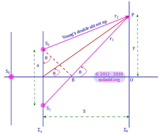
Let us consider two secondary coherent sources S1 and S2 which are distances r1 and r2 apart from the point of observation P. The path difference of these two rays is given by S1B = S1P – S2P.
Now S1B = r1 – r2 = a sin θ. This implies: r1 – r2 = a θ when angle θ is small. This also means θ = y / S. So: r1 – r2 = ( a / S ) y.
Constructive interference occurs when path difference is an integral multiple of λ. Thus: r1 – r2 = m λ, where m is any integer; 0, ± 1, ± 2, ± 3 …. So the height of observation point y can be given in terms of S: the distance of plane of observation Σo from screen of the sources Σa, here a: width between sources S1 and S2, m: order of interference, this is any integer and λ: the wavelength of the light sources.

Thus ym gives the position of the m-th order maxima or bright fringe, on the vertical axis. Since y = 0 for m = 0, we see a central bright fringe. The angular position of the m-th order bright fringe is given by: 
Two consecutive maxima are given by the integers m + 1 and m. So, we can easily determine the spacing between bright fringes. 
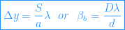
where we have given the fringe spacing an alternative symbol used in some textbooks: βb is fringe spacing for bright fringes, D is distance of separation between sources and the screen of observation, d is the slit separation.
Similarly dark fringes or minima are formed when the path difference is odd integer multiple of λ/2 or phase difference is odd integer multiple of π.
We can thus write: 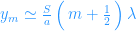
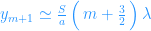
So

We see that the spacing between dark and bright fringes is the same and it remains constant even if we change the order of the interference: m.
When we studied interference due to two coherent plane harmonic waves, in lecture VII, we derived the intensity distribution for two beams having equal irradiance; 
By using r1 – r2 = ( a / S ) y we have: 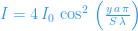
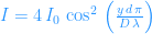
Let us plot this distribution as a function of y.


Leave a comment