Optics series, lecture – XIV, XV, XVI
These lectures were delivered on 16th and 21st February and on 17th March 2017 ( 1.5 hours each ) to honors as well as elective students
( all optics series lectures ) Go to other available optics lectures
“Interference by wave front and amplitude splitting”
Topics covered in this lecture
A. Color of thin films
B. Newton’s rings
C. Lloyd’s mirror and
D. Phase changes during reflection
Background
We have previously discussed what is interference and what are wave-front splitting and amplitude splitting interference. We have also discussed in much details two wave-front splitting interference viz.
a. Young’s double slit interference – in lecture — IX, and
b. Fresnel’s bi-prism – in lecture – XI.
( lecture 7 ) Go to interference lecture
( lecture 9 ) Go to Young’s double slit experiment
( lecture 11 ) Go to Fresnel’s bi-prism lecture
Today we will discuss one more wave-front splitting interference namely Lloyd’s mirror interference followed by the amplitude splitting interference of the Newton’s rings.
Also we will discuss two interesting and related concepts;
i. Phase change on reflection and ii. Color of thin films
Interference in Lloyd’s Mirror
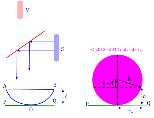
The Lloyd’s mirror is a set-up for wave-front splitting interference. Here two rays one of which undergoes reflection from a reflecting surface such as a mirror, meet up at the point of observation and subsequently interfere.
The interference pattern that is produced in a Lloyd’s mirror interferometer is complimentary to the pattern produced in a Young’s interferometer. That is because of an additional phase change of 
That means instead of a central bright fringe we obtain a central dark fringe.
a. The positions where minima are obtained in the Young’s double slit set-up are the positions where maxima are obtained in the Lloyd’s set-up.
b. Similarly the positions where maxima are obtained in the Young’s double slit set-up are the positions where minima are produced in the Lloyd’s set-up.
c. Only top half of the interference fringes in Lloyd’s set-up are visible as the bottom half is occluded by the mirror.

Lets look at the above diagram which depicts the Lloyd’s mirror set-up.
Here 
Here we would have the same fringe spacing as that found in the Young’s Double Slit interferometer, viz. 


( lecture 9 ) read Young’s double slit interference
All other derivation for Young’s double slit interference and Lloyd’s mirror interference are exactly same, except there is an additional phase change of 
For glaring incidence that is for 


We will soon see this result in the concurrent lecture, when we discuss phase change during reflection, by Stoke’s treatment. The path difference is 


Corresponding to this path difference we obtain the phase difference, by multiplying the path difference to the wave number k. There is an additional phase difference of
So total incumbent phase difference is 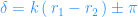


( lecture 7 ) Go to interference lecture
We know that
a. Crystals reflect x-rays
b. Mirrors reflect ordinary light, and
c. Wire-mesh reflect microwaves
In all of these cases Lloyd’s like interference is formed. Earth’s ionosphere reflecting radio-waves is also an example of Lloyd’s interference.
Before turning our attention to yet another example of interference, the Newton’s rings, which are formed via amplitude splitting interference lets discuss two important results that we will find useful many times during our discussions in optical phenomena.
a. one of this is the phase change during reflection and
b. the other is the phase difference in amplitude splitting phenomena and formation of color in thin films.
Phase change during reflection, Stoke’s treatment
In order to study the phase change during reflection and excavate the underlying relations by Stoke’s treatment, we need to state the principle of optical reversibility first.
According to “principle of optical reversibility” in the absence of absorption, a light ray when reflected or refracted, would retrace its original path, if the direction of ray incidence is reversed.
Let us apply this principle to the situation depicted in the diagram.

- Let the first medium be represented by refractive index
and the second medium — at the bottom, be represented by refractive index
in both fig 1 and fig 2.
- Let r and t be the fraction of amplitude that gets reflected or transmitted — i.e. refracted, respectively, for medium 1. These are also called as reflection coefficient of the amplitude and transmission coefficient of the amplitude.
- Similarly we need to define these parameters for the additional media which are different in general. Let r’ and t’ be those parameters for the 2nd medium, that is the medium with refractive index
.
We are following a color code in the diagram to easily follow which ray gets reflected to which medium and which gets transmitted to which, so as to write their amplitudes in the specified color for that ray as well as the same color for drawing the rays.
( our color coding scheme is applied from this point until mentioned otherwise )
e.g. in fig 2 the ray denoted as ar is the incident ray drawn in green, so ar is also written in green. Its easy to see from the green color with ar that this ray gets reflected to a ray in medium 1 with color red. So its resulting amplitude is ar × r = ar2, where ar is written in green and r is written in red.
The color code is applied to all the other rays in this way.
Let a ray with amplitude a be incident from medium 1 on medium 2 and partly reflected and partly refracted. Thus according to our notations and color coding the amplitude of the reflected ray would be: ar and the amplitude of the refracted ray would be: at.
Let us reverse the directions of the rays. Ray of amplitude at would be incident from medium 2 on medium 1. Thus the amplitude of the reflected ray would be: atr’ = atr’. Similarly the amplitude of the transmitted or refracted ray from at would be: att’ = att’.
Let us reverse the direction of ray with amplitude ar which is incident from medium 1 on medium 2. The reflected amplitude now would be: arr = ar2. Similarly refracted amplitude would be: art = art.
( our color coding scheme is applied to this point and no further )
According to principle of reversibility the two rays of amplitude ar2 and att’ must combine to give the incident ray of amplitude a.
So we have: ar2 + att’ = a.
This gives us:

Also two rays of amplitude atr’ and art must cancel each other.
I.e. atr’ + art = 0.
This gives:

We see from equation – 2 that there is a relative phase change of
Thus if the phase change of
Equations – 1 and – 2 are known as Stoke’s Relations.
Color of thin films
When light falls on a thin film whose thickness is of comparable dimensions to the wavelength of light, due to interference between light reflected from the top surface of the film and light refracted into the film and reflected from the back surface color fringes are produced.
We will consider parallel films for the time being. A rigorous discussion for non-parallel or wedge shaped films is to be expected in the near future.
- In some situations where we will find applications of the following results we will consider near normal incidence because this makes the visibility of the fringes more likely if we are focused on a slightly larger region of the film.
- Newton’s Rings that we will study next assumes near normal incidence of the result that we will just derive.

Let us calculate the optical path difference between the 1st reflected ray — i.e. the one from the top surface and the 2nd reflected ray — i.e. the one from the bottom surface.
Optical Path Length ( hence forth OPL ) difference = Γ.

Its easy to see from symmetry that 


If we draw a perpendicular from 


Let us apply Snell’s law, which says 

![\Gamma = 2\,n\,d \Big[ \frac{1}{\cos\beta}-\tan\beta \sin\beta\Big]](https://s0.wp.com/latex.php?latex=%5CGamma+%3D+2%5C%2Cn%5C%2Cd+%5CBig%5B+%5Cfrac%7B1%7D%7B%5Ccos%5Cbeta%7D-%5Ctan%5Cbeta+%5Csin%5Cbeta%5CBig%5D&bg=ffffff&fg=1e90ff&s=0&c=20201002)
Its easy to see from here using only the basic trigonometric identities that the term inside the square brackets is nothing but 
Depending on various situations of value of refractive indices of the 3 media ( the media on both sides of the thin film can in general be considered different ) there is an additional phase change of
As we have seen in the last section, only for reflection from denser medium there is an abrupt change of phase of
a. one where it does not introduce a phase shift and
b. one where reflection introduces a phase shift of
Let us write the conditions of maxima and minima accordingly.
a. If 

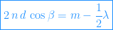
b. If 
Newton’s Rings
Now we are in a situation to study an interference pattern that arises due to amplitude splitting interference that we just studied in the last section, viz. the color of thin films.
The Newton’s rings are a pattern of circular bright and dark fringes, which are formed when an almost monochromatic light falls on a combination of two refracting and reflecting surfaces. There is an optical path length difference which is introduced to one of the rays, due to thickness of refracting medium, d, between the surfaces. The reflected and refracted rays eventually meet up and given to the mechanism of amplitude splitting interference the fringes are produced.

Let us consider a Plano-convex lens of radius of curvature R which is placed on an optically flat surface POQ.
In the last section we have derived the optical path length difference introduced due to such refracting and reflecting pair of rays — i.e. 1st order reflected ray and 2nd order reflected ray. We saw that the OPL difference was given by 
We consider only near normal incidence. In a later lecture we will see that this enhances our chances to see the fringes in a wider region. Accordingly the incident angle and refracted angle will be both small and 

Let us draw a suitable diagram for better grasping of the situation here.

The point of contact of the two glasses acts like a center of the circular fringes and the thickness of air film between AOB and POQ is constant on circles of radius 
Total destructive interference or minima occur such that 

Similarly the total constructive interference or maxima occur such that 
Remember that the conditions of maxima and minima are reversed compared to ordinary situations because there is reflection from a denser medium which introduces additional phase shift of
The circular fringes thus produced are known as Newton’s rings.
For more details on total constructive and total destructive interference, check the earlier linked lecture — VII.
Let us look at the RHS of the diagram above.
We apply Pythagoras theorem on the circular cross section as shown.
We have 
Typically 


This leads us to 

For dark fringes 


Between two dark fringes we would see a bright fringe whose radius is proportional to 


But if we measure the fringes at intervals of p instead of a value of 1, such that usually 

We can write more conveniently: 
If instead of air we use material of refractive index n then the expression for dark fringes changes accordingly to: 

Leave a comment