Optics series, lecture – VII
This lecture was delivered on 7th February 2017 ( 1.5 hours )
( all optics series lectures ) go to other available optics lectures
“Conditions of interference: interference of two harmonic plane waves”
Electromagnetic waves
Light is an electromagnetic ( EM ) wave. In-fact its a transverse electromagnetic wave which means the oscillation of E and B fields produces light which propagates in a direction that is perpendicular to the plane that contains the E and B fields. In other words E, B and k ( the wave – vector: that denotes the direction of light propagation ), are mutually perpendicular vectors.
We will study these details in a later lecture ( see link below ). EM waves are not only transverse waves but also vector waves, that is; E and B are vector fields whose undulation is summarized as light.
( Details of electromagnetic waves ) click to read more about electromagnetic waves
Light is a general name for all EM waves but visible light is that particular part of EM waves which has frequency of wave such that the wavelength varies from approximately 400 – 700 nm. Therefore light whose wavelength lies between 400 – 700 nm is called as visible light: we can write for vacuum c = ν λ. Thats because in vacuum ( and only in vacuum ) light always moves at a fixed speed: namely c = 3 × 10⁸ m/s.
Light as a transverse wave phenomenon of vector fields is comprehensively described by four equations known as Maxwell’s equations. The Maxwell’s equations are a summary of important and fundamental laws of electricity and magnetism — together called as electromagnetism. This includes laws such as Gauss law and Ampere’s law. These equations produce the wave equation of motion, a linear, homogeneous, 2nd order differential equation.
Here is more about wave equation.
( What are waves? ) click to read more about waves
If you are interested you can also have a look at the details of Maxwell’s equations and exactly how these turned into wave equations. But these are advanced treatments and some of you will be studying these as required course in your final years. See links below.
( Maxwell’s equations ) click to read more about Maxwell’s equations
( An advanced treatment for em waves) click to read more
You can also follow my slide-shares:
( Click to get some more resources in physics ) click to read more
( read more detailed analysis of electromagnetic waves ) click to read more
Let us therefore write the wave equation of motion, where the 3 components of the E field — such as Ex, Ey or Ez or the 3 components of B field such as Bx, By and Bz are denoted as ψ chosen anyone at one time. eg we can chose Ex = ψ.
In general we have: 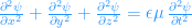

So ψ is any one of the scalar component of any vector field E or B. Also ε, μ are the permittivity and the permeability respectively of any medium so that ε μ = 1/v2 with the recognition that v is the speed of wave propagation, entailed by the above wave equation. Needless to say, if the wave travels in free-space — or vacuum, we replace the above equation with the proper subscripts that represents the quantities in free space. We have for free space: ε0 μ0 = 1/c2.
Harmonic plane waves
Let us now consider two monochromatic point sources S1 and S2 in a homogeneous medium. A monochromatic source would mean a single wavelength and a single frequency. Homogeneous media are those where physical properties do not change from one point to another.
Let the sources be a distance a apart from each other so that the wave length of light is negligible compared to this distance. That is; a >> λ, where λ is the wavelength of the light emitted from S1 or S2. In our earlier lectures we learned a similar condition as the geometrical optics or ray optics limit.
Let the light emitted from these sources meet at point P. Lets consider only linearly polarized light. That is there is a fixed plane instead of arbitrarily many planes on which the E field — and correspondingly the B field, oscillate.
Let us now draw a suitable diagram for our situation.

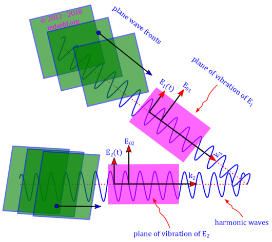
Let us consider what happens when the two plane harmonic waves from monochromatic sources S1 and S2 reach the point P. When two waves reach the same space-point they can together be described by the principle of superposition.
According to the principle of superposition: two different vectors or scalars are added to determine the combined effect. Here we are considering the oscillation of the electric field vector of the plane wave-fronts — given as E1(t) and E2(t) in the diagram whose amplitude ≡ maximum oscillation value, is independent of time and space points and is given as E01 and E02 in the diagram.
Accordingly we write the effective electric field vector E at the point P as the sum of the individual electric field vectors E1(t) and E2(t) and explicitly write their harmonic monochromatic form. Harmonic means sine or cosine or a combination of both and monochromatic means single wavelength, for both sources which also means the same value for frequency ω for both wave as shown below.
Principle of superposition: 


Interference
Interference of optical waves can be defined in terms of irradiance I which is the amount of optical energy falling on an unit surface area in an unit time. If the energy is emitted out of the surface its called as exitance. But radiant flux density is the general name for both irradiance ( falling on the surface) or exitance ( emission out of the surface ).
The irradiance can be written as I = εv〈 E2〉 T where T is time elapsed, such that the time period of light wave τ is far smaller than this elapsed time T and we can write: T >> τ. The factor in front of the expression: εv is constant for a homogeneous medium. We will disregard this factor, as its same for all waves for calculating irradiance. Thus for our analysis irradiance would be given as: I = 〈 E2〉 T.
Let us define optical interference as the interaction of two or more light waves such that resultant irradiance is different from sum of the individual irradiances. From superposition of the waves in terms of electric field vectors: E(t) = E1(t) + E2(t) hence 

But we see that: 
This leads to ![\vec{E}_1\cdot\vec{E}_2=\vec{E}_{01}\cdot\vec{E}_{02}\times\big[\cos{\,} (\vec{k}_{1} \cdot\vec{r}\,+\, \epsilon_{1})\,\cos\,\omega t \,+\,\sin{\,} (\vec{k}_{1}\cdot\vec{r}\,+\, \epsilon_{1})\,\sin\,\omega t\big] \times \big[\cos{\,} (\vec{k}_{2}\cdot\vec{r}+ \epsilon_{2}) \,\cos\,\omega t +\sin{\,} (\vec{k}_{2}\cdot\vec{r}+ \epsilon_{2})\,\sin\,\omega t\big]](https://s0.wp.com/latex.php?latex=%5Cvec%7BE%7D_1%5Ccdot%5Cvec%7BE%7D_2%3D%5Cvec%7BE%7D_%7B01%7D%5Ccdot%5Cvec%7BE%7D_%7B02%7D%5Ctimes%5Cbig%5B%5Ccos%7B%5C%2C%7D+%28%5Cvec%7Bk%7D_%7B1%7D+%5Ccdot%5Cvec%7Br%7D%5C%2C%2B%5C%2C+%5Cepsilon_%7B1%7D%29%5C%2C%5Ccos%5C%2C%5Comega+t+%5C%2C%2B%5C%2C%5Csin%7B%5C%2C%7D+%28%5Cvec%7Bk%7D_%7B1%7D%5Ccdot%5Cvec%7Br%7D%5C%2C%2B%5C%2C+%5Cepsilon_%7B1%7D%29%5C%2C%5Csin%5C%2C%5Comega+t%5Cbig%5D+%5Ctimes+%5Cbig%5B%5Ccos%7B%5C%2C%7D+%28%5Cvec%7Bk%7D_%7B2%7D%5Ccdot%5Cvec%7Br%7D%2B+%5Cepsilon_%7B2%7D%29+%5C%2C%5Ccos%5C%2C%5Comega+t+%2B%5Csin%7B%5C%2C%7D+%28%5Cvec%7Bk%7D_%7B2%7D%5Ccdot%5Cvec%7Br%7D%2B+%5Cepsilon_%7B2%7D%29%5C%2C%5Csin%5C%2C%5Comega+t%5Cbig%5D+&bg=ffffff&fg=1e90ff&s=0&c=20201002)
From elementary calculus we know that the average of sine and cosine functions over complete periods, when the functions are squared, is one-half. Also the average over complete periods of sine and cosine functions is zero.
So we have: ![\langle\vec{E}_1\cdot\vec{E}_2\rangle_T =\frac{1}{2}\, \vec{E}_{01} \cdot\vec{E}_{02}\,\big[\cos{\,} (\vec{k}_{1}\cdot\vec{r}+ \epsilon_{1}-\vec{k}_{2} \cdot \vec{r}-\epsilon_{2})\big]](https://s0.wp.com/latex.php?latex=%5Clangle%5Cvec%7BE%7D_1%5Ccdot%5Cvec%7BE%7D_2%5Crangle_T+%3D%5Cfrac%7B1%7D%7B2%7D%5C%2C+%5Cvec%7BE%7D_%7B01%7D+%5Ccdot%5Cvec%7BE%7D_%7B02%7D%5C%2C%5Cbig%5B%5Ccos%7B%5C%2C%7D+%28%5Cvec%7Bk%7D_%7B1%7D%5Ccdot%5Cvec%7Br%7D%2B+%5Cepsilon_%7B1%7D-%5Cvec%7Bk%7D_%7B2%7D+%5Ccdot+%5Cvec%7Br%7D-%5Cepsilon_%7B2%7D%29%5Cbig%5D&bg=ffffff&fg=1e90ff&s=0&c=20201002)
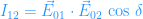
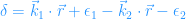
Here δ is the phase difference arising from both path length differences and initial phase difference. If the waves emanated from the sources are such that the electric field vectors oscillate in the same direction ( known also as linear polarisation ) then: 
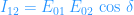


So the total irradiance equals to the individual irradiances and the interference term; 
Constructive and destructive interference
- Total constructive interference
- in the above equation we see that maximum irradiance occurs when cos δ is 1;
, this represents the condition of total constructive interference and it is possible when phase difference δ equals angles that are integral multiples of 2 π. i.e.
. In this situation the waves from different sources are said to be in phase. The troughs overlap with troughs and crests overlap with crests.
- Constructive interference
- when cos δ is between 0 and 1 waves are still partially in phase — that is not completely out of phase, such a situation is known as constructive interference. In this case: I1 + I2 < I < Imax.
- No interference
- when δ = π/2, i.e. cos π = 0, that is optical disturbances are 900 out of phase this implies I = I1 + I2.
- Condition of destructive interference
- when cos δ lies between 0 and – 1, that is: 0 > cos δ > – 1 waves are partially out of phase. This is known as the condition of destructive interference. We have I1 + I2 > I > Imin.
- Total destructive interference
- minimum amount of irradiance occurs when waves are 1800 out of phase, the troughs overlap with crests and vice-a-versa. cos δ is -1.
, this occurs when the phase difference is equal to odd integral multiples of π … i.e.
. This is known as total destructive interference.
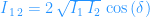
- Amplitudes of the two sources are same
- when amplitudes of the source S1 and S2 are the same that is if E 01 = E 02 then I1 = I2 = I0, in this case the total irradiance, the minimum irradiance and the maximum irradiance are as follows:
and
.

Leave a comment