Analog systems and applications — lecture – XXIII.
RC coupled single stage amplifier and its low frequency response, Lecture – 23.
This article belongs to a series of lectures on analog electronics, the paper goes by the name “Analog Systems and Applications” for the physics honors degree class. All lectures of this series will be found here. This is the 23rd lecture of the series. The lecture was delivered on 29th March 2018.
In our last two lectures we discussed in much detail the case of the single stage common emitter RC coupled amplifier. There we discussed the elements of the circuits (such as why a given capacitor is required and so on), determined the currents in various components (such as base and collector) and eventually calculated the current, voltage and power gain of such an amplifier. In doing so we employed the hybrid or equivalent circuit analysis method.
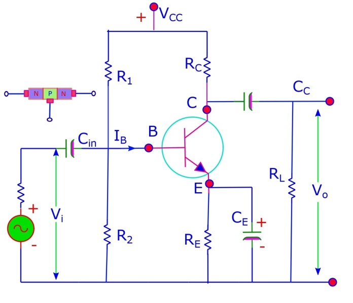
Today we would like to delve on the subject a little deeper and see what exactly is the response of a single stage RC amplifier to a given frequency. Let us remember the diagram that represented the circuit for this amplifier (taken from first of the last two lecture, linked above).
The common emitter circuit single stage amplifier. It consists of specially placed resistors for voltage divider type bias and capacitors for achieving desired actions.
Frequency response of a single stage RC amplifier.
Lets define three frequency regions.
- Low: if the frequency is less than 50 Hz.
- Medium: If the frequency is between 50 Hz to 20 kHz.
- High: If the frequency is larger than 20 kHz.
Mid frequency range:
All the capacitors: Cin, CC and CE are assumed large so that their reactance [1/(ωC)] can be assumed to be negligibly small. In-fact we have already assumed the mid-frequency region, in our analysis of the circuit (in our last lectures) and accordingly we obtained the voltage gain for such an amplifier as follows: 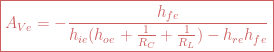
The voltage gain is independent of frequency in the mid frequency zone.
lets see whats it like with the low frequency
Low frequency range:
Series reactance of the coupling capacitor [1/(ωCC)] is no more negligible. The emitter capacitor (CE) and the input capacitor (Cin) are assumed to have large values. As a result their reactance can be safely neglected and that means they provide a conducting path (like a short).
Low-frequency single stage RC coupled amplifier.
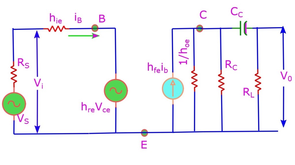
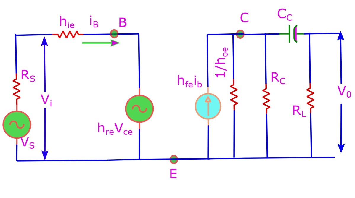
Lets now draw the AC equivalent circuit for the low-frequency single stage RC coupled amplifier.
The low frequency RC coupled amplifier in its hybrid or equivalent circuit form. Note how there is an extra capacitor now compared to the circuit we drew for it for mid-frequency in our last two lectures. Now this comes in between the two resistors which were earlier dealt as parallel giving an effective AC resistance Rac. Now the equations are going to be different because of this altered scenario.
Lets apply Kirchhoff’s voltage law in the input circuit: Vi – hreVce = iBhie. eqn 1
Lets apply Kirchhoff’s current law at node C: hfeiB + hoeVo + Vce/RC + jωCC (Vce – Vo) = 0. eqn 2
The same AC current passes through CC and RL (as they are in series) ⇒ jωCC (Vce – Vo) = Vo/RL. eqn 3
We can solve for Vi and Vo in eqn 1 and eqn 2 using eqn 3 and from this we obtain the expression for voltage gain. ![\boxed{A_{Ve} = -\frac{h_{fe}}{h_{ie}(h_{oe} +\frac{1}{R_C}+ \frac{1}{R_L})-h_{re}h_{fe}-j\frac{[h_{ie}(h_{oe} +\frac{1}{R_C})-h_{re}h_{fe}]}{\omega C_C R_L}}}](https://s0.wp.com/latex.php?latex=%5Cboxed%7BA_%7BVe%7D+%3D+-%5Cfrac%7Bh_%7Bfe%7D%7D%7Bh_%7Bie%7D%28h_%7Boe%7D+%2B%5Cfrac%7B1%7D%7BR_C%7D%2B+%5Cfrac%7B1%7D%7BR_L%7D%29-h_%7Bre%7Dh_%7Bfe%7D-j%5Cfrac%7B%5Bh_%7Bie%7D%28h_%7Boe%7D+%2B%5Cfrac%7B1%7D%7BR_C%7D%29-h_%7Bre%7Dh_%7Bfe%7D%5D%7D%7B%5Comega+C_C+R_L%7D%7D%7D+&bg=ffffff&fg=cd5c5c&s=2&c=20201002)
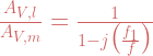
Now we can compare the voltage gain at low frequency to that at the mid frequency region.
![\boxed{\frac{A_{V,l}}{A_{V,m}}=\Bigg[1-\frac{j[h_{ie}(h_{oe} +\frac{1}{R_C})-h_{re}h_{fe}]}{2\pi f C_C R_L[h_{ie}(h_{oe} +\frac{1}{R_C}+ \frac{1}{R_L})-h_{re}h_{fe}]}\Bigg]^{-1}}](https://s0.wp.com/latex.php?latex=%5Cboxed%7B%5Cfrac%7BA_%7BV%2Cl%7D%7D%7BA_%7BV%2Cm%7D%7D%3D%5CBigg%5B1-%5Cfrac%7Bj%5Bh_%7Bie%7D%28h_%7Boe%7D+%2B%5Cfrac%7B1%7D%7BR_C%7D%29-h_%7Bre%7Dh_%7Bfe%7D%5D%7D%7B2%5Cpi+f+C_C+R_L%5Bh_%7Bie%7D%28h_%7Boe%7D+%2B%5Cfrac%7B1%7D%7BR_C%7D%2B+%5Cfrac%7B1%7D%7BR_L%7D%29-h_%7Bre%7Dh_%7Bfe%7D%5D%7D%5CBigg%5D%5E%7B-1%7D%7D+&bg=ffffff&fg=cd5c5c&s=2&c=20201002)
We see that voltage gain at low frequencies is less than voltage gain at mid frequencies. Also this further decreases with decrease in frequency.
Lower cutoff frequency f1 is defined as that value of frequency at which voltage gain is 1/√2 times mid frequency voltage gain. Thus power gain is 1/2 times mid frequency power gain, at this value of low frequency signal. i.e. at f = f1, |AV,l / AV,m| = 1/√2 and PV,l / PV,m = 1/2.
![\boxed{f=f_1=\frac{[h_{ie}(h_{oe} +\frac{1}{R_C})-h_{re}h_{fe}]}{2\pi f C_C R_L[h_{ie}(h_{oe} +\frac{1}{R_C}+ \frac{1}{R_L})-h_{re}h_{fe}]}}](https://s0.wp.com/latex.php?latex=%5Cboxed%7Bf%3Df_1%3D%5Cfrac%7B%5Bh_%7Bie%7D%28h_%7Boe%7D+%2B%5Cfrac%7B1%7D%7BR_C%7D%29-h_%7Bre%7Dh_%7Bfe%7D%5D%7D%7B2%5Cpi+f+C_C+R_L%5Bh_%7Bie%7D%28h_%7Boe%7D+%2B%5Cfrac%7B1%7D%7BR_C%7D%2B+%5Cfrac%7B1%7D%7BR_L%7D%29-h_%7Bre%7Dh_%7Bfe%7D%5D%7D%7D+&bg=ffffff&fg=cd5c5c&s=1&c=20201002)

Then at f = f1, |AV,l / AV,m| = 1/√2 = 0.707 ≡ 70.7 % according to our conjecture. Overall phase shift of voltage gain in low frequency range is given as: φl = 1800 + θl = 1800 + tan-1 (fl/f). At f = f1, φl = 1800 + 450 = 2250.
In this high pass RC filter 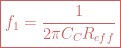
Then ![\boxed{R_{eff}=\frac{[h_{ie}(h_{oe} +\frac{1}{R_C} + \frac{1}{R_L})-h_{re}h_{fe}]R_L}{2\pi f C_C R_L[h_{ie}(h_{oe} +\frac{1}{R_C})-h_{re}h_{fe}]}}](https://s0.wp.com/latex.php?latex=%5Cboxed%7BR_%7Beff%7D%3D%5Cfrac%7B%5Bh_%7Bie%7D%28h_%7Boe%7D+%2B%5Cfrac%7B1%7D%7BR_C%7D+%2B+%5Cfrac%7B1%7D%7BR_L%7D%29-h_%7Bre%7Dh_%7Bfe%7D%5DR_L%7D%7B2%5Cpi+f+C_C+R_L%5Bh_%7Bie%7D%28h_%7Boe%7D+%2B%5Cfrac%7B1%7D%7BR_C%7D%29-h_%7Bre%7Dh_%7Bfe%7D%5D%7D%7D+&bg=ffffff&fg=cd5c5c&s=1&c=20201002)
Usually output admittance (hoe) and reverse voltage ratio (hre) are very small. In that situation: 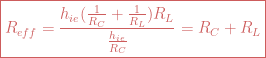
We see that the effective resistance Reff for lower half-power frequency f = f1 is the series addition of resistances on both sides of the capacitance CC, i.e. RC and RL.

Leave a comment