Analog systems and applications — lectures – XXVIII, XXIX.
This article belongs to a series of lectures on analog electronics, the paper goes by the name “Analog Systems and Applications” for the physics honors degree class, — click on link to left to access all lectures of this series. This article comprises of the 28th and 29th lecture of the series. The lectures were delivered on 4th April 2018.
Feedback Amplifiers, Lectures – 28, 29.
We have reached our final lectures of this series. (Counting the complimentary lecture of Norton’s and Thevenin’s theorem this takes the number of lectures to 30). Some more lectures could have been delivered in the class room but the terrain wasn’t quite welcoming for that ambition/requirement. When priorities are available (which could be years in itself) some of the most important lectures for this course, as well as the ones that completes a good list of course lectures might be added.
In our last two lectures we studied in good detail the classification of the power amplifiers and how they perform etc. Today’s two lectures will be exposited upon the concepts of feedback amplifiers. While this is not comprehensive in any way as there could be a lot more that could be said about this expanding topic, this is nonetheless a good solid foundational step upon which a first timer yet prepared apprentice can lean back.
Feedback amplifiers
Feedback
Feedback in an electronic device is a process, in which part of the output energy, in the form of either a current or a voltage signal is supplied back into the input. The input is driven by the output and in turn the input controls the output.
Negative feedback
In this process the output feedback opposes the input signal, due to phase difference. For this reason it is known as inverse, degenerative or negative feedback. Gain of the amplifier is reduced. Band width which denotes the range of uniform amplification is increased, thus the stability of the feedback amplifier is increased. Negative feedback reduces the amplitude, frequency, phase distortion and the noise level of the output. Negative feedback is thus a preferable feature in an amplifier.
Positive feedback
In this process the output feedback is in phase with the input signal. Thus it aids the input signal. It is therefore known as direct, regenerative or positive feedback. In this case the gain of the amplifier, is increased. But the band width, distortion and noise are not favorable: band width decreases where as distortion and noise increase. Also stability is decreased in positive feedback. Positive feedback is not very preferable for this reason. When feedback energy is large, positive feedback amplifiers act as oscillators.
Sampling
It is the process by which a continuous part of the output signal is passed to input through a feedback network.
- Current Sampling: it is always done in series in the output circuit as shown in the following diagram.
- Voltage Sampling: similarly voltage signal is always sampled by shunting, i.e. by using parallel connections across the output.
Sampling means therefore taking a sample of the signal or part thereof from the output as its source.
Remember: Voltage sampling is always shunted or parallel and current sampling is always in series.


Summing
The output of feedback network — which was proportional to the output of the amplifier, is mixed with the input (of the amplifier) in two ways. The concepts are depicted in the following diagram.
- Voltage Mixing: in voltage mixing feedback signal voltage drawn from output through feedback network (via shunt connection) and source voltage for signal in input are connected always in series.
- Current Mixing: similarly in current mixing (or summing), feedback current (drawn from output (by series connection) is always mixed or summed in parallel or shunt connection with current source.
Thus voltage mixing is known as series mixing and current mixing is known as shunt mixing.
Know more about voltage and current sources here to see why this is so, in this article.


- voltage feedback: voltage signal to be fed to input is proportional to output voltage across load impedance.
- current feedback: voltage signal to be fed is proportional to current of output and independent of load impedance.
In both cases its is the voltage signal only which is fed-back.
Types of feedback connections
- When feedback quantity is connected in series with input source, irrespective of sampling type (voltage or current) then it has to be a voltage. Current signal can’t be connected in series with current source.
- If feedback quantity is shunted (i.e. parallel) with input source, it must be a current signal, irrespective of whether the sampling is voltage or current sampling (i.e. series or parallel). So a voltage signal can’t be connected in parallel (or be shunted) across input source, which is a voltage source.
Consequently there are 4 basic types of feedback amplifiers.
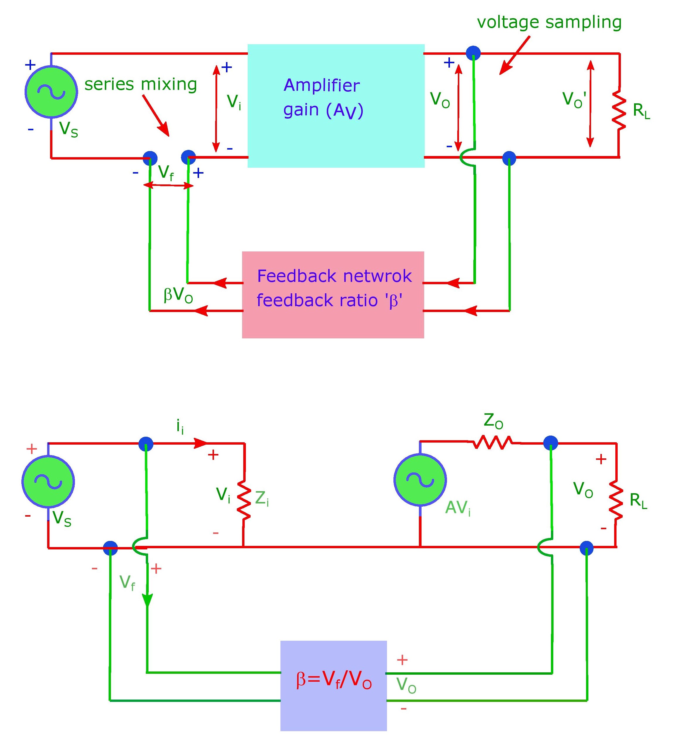
Voltage-Series feedback amplifier
In this case a voltage sampling (always parallel) is fed into a voltage source (which must be in series). Thus Voltage-sampling + Series mixing leads to the name “Voltage Series Feedback Amplifier“. For the same reason its known as Series-Shunt (input in Series and Output in Shunt) or Series-Parallel Feedback Amplifier abbreviated as SP Feedback Amplifier.
It is a voltage amplifier and therefore known as Voltage-Voltage converter. It has high input impedance and low input impedance. Due to feedback input impedance increases by the factor: 1 + β AV, the output impedance decreases by the same factor. β is known as feedback ratio and is given by: Vf / Vo. is the voltage gain of the amplifier without feedback, see these articles how amplifier voltage gain has been calculated for various amplifiers: low, medium, high.
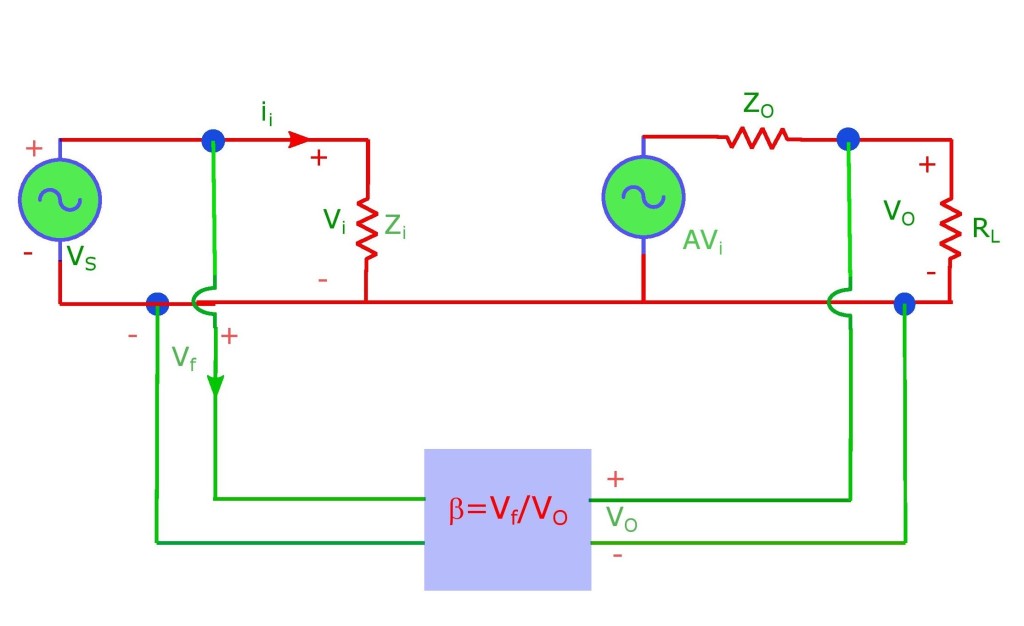
Below is the diagram which depicts various concepts associated with this type of feedback amplifier (Voltage-Series type).
Analysis
Let Zi be the input impedance without feed. ii = Vi/Zi. But Vo = AVi. In general A is transfer function. Here voltage signal (from output i.e. Vo) is fed to input voltage signal Vi. ⇒ A = Vo/Vi. Also from definition of β, Vf = βVo. ⇒ ii = (Vs – βVo)/Zi = (Vs – AβVi )/Zi or iiZi = Vs – AβVi. ⇒ iiZi = Vs – AβiiZi ⇒ Vs = ii Zi(1+ Aβ).
Input impedance with feedback, Zif = Vs/ ii = Zi(1 + Aβ). Thus Zif increases by factor (1 + Aβ) wrt Zi. For output impedance, applying voltage V, a current i results, when Vs = 0. At input: Vs = 0, Vi = – Vf. At output: V = iZo + AVi = iZo – AVf = iZo – AβV, iZo = V + AβV = V(1+βV). Thus Zof = V/i = Zo/(1 + βV). It (Zof) decreases by factor (1+ Aβ), wrt output impedance without feedback (i.e. Zo).
Voltage-Shunt Feedback Amplifier
Here a voltage voltage from output (hence a voltage sampling or shunted output) is connected across (i.. shunted) to input source. This must be a current source, as we have discussed earlier. For similar reasons, as discussed in the connection type discussed above, this is called a PP feedback (for parallel-parallel), Shunt-Shunt feedback amplifier or simply shunt feedback amplifier. It is a current-voltage converter or a trans-impedance amplifier. The following is a diagram that depicts the ideas of a PP feedback.
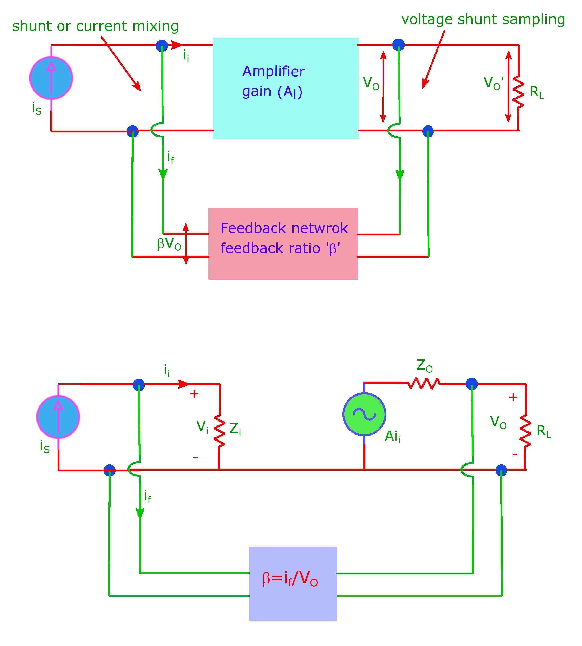
Analysis
Zm = Vo‘/ii, with RL→∞ (open circuit) is known as open circuit transfer impedance or trans-impedance.
With Zi the input impedance without feed, ii = Vi/Zi. if = βVo. A = Vo/ii. (As, here input is a current source: also note that definition of A and β change according to the type of feedback amplifier.) is = ii + if, in the input circuit. ⇒ input impedance with feedback: Zif = Vi/is = Vi/[ii(1 + Aβ)] = (Vi/ii)/(1 + Aβ) = Zi/(1 + Aβ).
Output impedance. Here is = 0 for input circuit/port: ii = – if = -βV. Output port: V = iZo + Aii = iZo – βAV ⇒ i = V(1 + Aβ)/Zo and Zof = V/i = Zo/(1 + Aβ). Both input and output impedance reduce by a factor of 1 + Aβ due to feedback.
Homework: do the same analysis for current-series and current-shunt feedback cases. Draw 2 diagrams for each as we did for the above two cases.
Summary:
| Parameters | Voltage-Series | Voltage-Shunt | Current-Series | Current-Shunt |
|---|---|---|---|---|
| (I did) | (I did) | (homework) | (homework) | |
| A | Vo/Vi | Vo/ii | io/Vi | io/ii |
| β | Vf/Vi | if/Vo | Vf/io | if/io |
| Zif | Zi(1+ Aβ) | Zi/(1+ Aβ) | Zi(1+ Aβ) | Zi/(1+ Aβ) |
| Zof | Zo/(1+ Aβ) | Zo/(1+ Aβ) | Zo(1+ Aβ) | Zi/(1+ Aβ) |
Amplifier gain due to feedback
Lets consider the Voltage-Series feedback amplifier, as we discussed in our first connection type above. Here the voltage gain of the amplifier without the feedback is given by: AV = Output voltage / Input voltage = Vo/Vi = Vo/Vs. It is called open loop gain, as feedback network loop is not connected to the amplifier input.
When the feedback network is connected, a fraction of output voltage Vo reaches the input. Let this be Vf. It has an opposite polarity wrt Vs, in case of Voltage-Series case, that we are discussing right now. Thus Vi = Vs – Vf. This changes output from Vo to Vo‘. Vi < Vs ⇒ Vo‘ < Vo.
‘β‘ known as “feedback ratio“ or reverse transmission of feedback network, is defined as feedback voltage value divided by output voltage value. Thus β = Vf/Vo‘. Effective input voltage to the amplifier is thus: Vi = Vs – βVo‘. This is amplified AV times, hence output voltage Vo‘ = AVVi = AV(Vs – βVo‘), or Vo‘/Vs = AV(1 + βAV). Vo‘/Vs is known as gain of the amplifier with feedback or closed loop gain. βAV is known as “return ratio” or “loop gain feedback factor” (or “loop transmission”). In general AV and β are complex values and functions of frequency of signal. 1 + βAV is known as “return difference”.
- if |1 + βAV|>1, AVf < AV ⇒ negative feedback.
- if |1 + βAV|<1, AVf > AV ⇒ positive feedback.
- if |1 + βAV|=0, AVf = ∞ ⇒ condition of oscillator (output is obtained without external signal source).
- if βAV >> 1, AVf = 1/β ⇒ large negative feedback.
- for positive feedback: AVf = AV/(1 – βAV).

Leave a comment